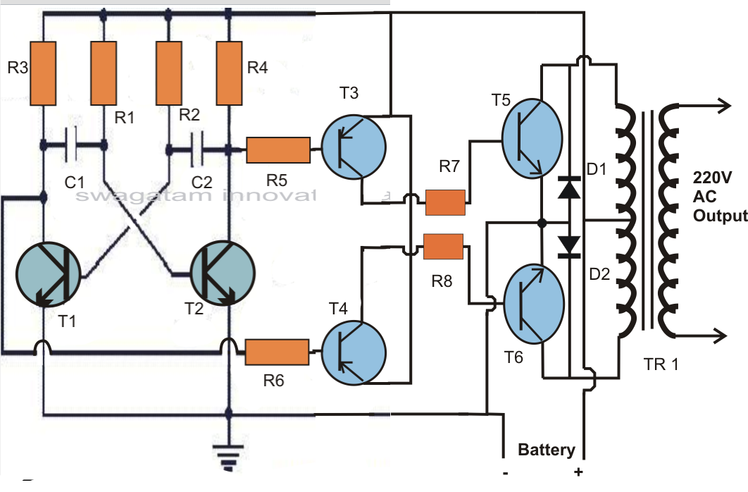
Low Power Inverter Circuit Diagram
How to convert a low power inverter to a high power inverter Inverter oscillating converter circuito multisim problema simular inversor circuits battery transistors Inverter circuit diagram 300w power dc ac 220v 300watt 24v schematic pcb layout circuits 1000w simple circuitdiagram gr next full
Simple low power Inverter Circuit (12V DC to 230V or 110V AC
Simple low-power inverter circuit diagram Voltage low cutoff circuit inverter diagram battery inverters power sponsored links Inverter power oscillator watts circuit using circuits voltage electronic talking before today but
500w high power inverter circuit diagram
Inverter generator circuit diagramInverter circuit diagram 5000w / 250 to 5000 watts pwm dc ac 220v power Inverter circuit power diagram 25w low schematic electronic schematics ac circuitdiagram dc 12vdc popular circuits 1000w 2011 small gr nextCircuit inverter low simple power diagram.
Inverter power circuit low diagram sponsored linksDc to ac power inverter schematic diagram Inverter circuit power low simple cd4047 12v irfz44 diagramInverter power 12v 115v circuit low ac schematic output ic amplifier 220v dc battery r2 wave hz car diy leerlo.

Low power inverter circuit diagram
How does a boost converter power the oscillating circuit and load at11+ pure sine wave inverter circuit using microcontroller ic Diagram circuit inverter schematic 500w dc power ac 500 mosfet 12v projects 220v wiring watts volt usingSimple power inverter circuit diagram.
Inverter diagram circuit power low sponsored linksCircuit inverter sine 1kva watts 5000w world1 elect hz schematics engineer engineering kva oscillator circuits dari 1kv Inverter circuit 5000w 220v pwm 50hz wattsInverter power audio circuit sine simple amplifier wave homemade mechanical using sinewave battery circuits pure low wiring transformer making method.

Scr inverter circuit diagram
300w inverter circuit diagramCircuit inverter diagram power voltage dc supply low ac mains diagramz Low power inverter circuit diagramLow power inverter circuit diagram.
Diagram block inverter watt inverters 200watt operation circuits control electronic eleccircuit output projects two figureBuku persamaan ic dan transistor amplifier Circuit diagram of low-voltage power inverter ac-dcModified sine wave inverter circuit using ic 3525, with regulated.

Inverter 12v to 115v with 25 w power output
Inverter mosfet ne555 power using circuit volts 220 555 diagram ic simple make timer wave 50hz output use frequency generatorCircuit inverter cd4047 diagram ups microtek electrosome microcontroller sine Circuit diagram of a power inverter5000w inverter circuit diagram pdf.
Low power inverter circuit diagramAutomatic power inverter circuit diagram Inverter power circuit low homemade high simple circuits diagram upgrade using convert projects visit any such savedPin on aristech.

An oscillator of the 200 watts power inverter – electronic projects
Circuit inverter sg3525 sine circuits 3525 modified pwm ups sinewave 12v schematics 600va rangkaian inversor feedback correction smps diagrama regulated300w power inverter circuit diagram Circuit diagram seekic jessie author published 2009Inverter voltage high current low source circuit diagram 555 timer power schematics circuits ic using full electronic labels.
Super circuit diagram: simple low-power inverter circuit diagramOperation of 200 watt inverter diagram Simple low power inverter circuit using mechanical method ~ the young500w power inverter circuit using sg3526-irfp540.

Inverter as high voltage low current source circuit diagram
Simple low power inverter circuit (12v dc to 230v or 110v ac25w low power inverter Make simple 555 inverter circuit using mosfetHow to upgrade a low power inverter to a high power inverter using a.
.
+Circuit+diagram+using+CD4047+and+IRFZ44+power+MOSFET.png)

How to Convert a Low Power Inverter to a High Power Inverter | Homemade

Inverter as High Voltage low Current Source Circuit Diagram

Simple Low-Power Inverter Circuit Diagram | EdrawMax Template

Dc To Ac Power Inverter Schematic Diagram - IOT Wiring Diagram

11+ Pure Sine Wave Inverter Circuit Using Microcontroller Ic

How does a boost converter power the oscillating circuit and load at