Load Combinator Circuit Diagram
Electrical circuit basics Electronic schematic circuits codrey lm358 Load combinator circuit diagram
Simplified circuit diagram of sampled resistive load | Download
Analog bits How to connect a load combinator to a load amplifier for load cells Try to understand this electronic load circuit
Load cell arduino noise problem uno amplifier instrumentation stack
Can someone explain this dc load circuit?Electronic – why aluminium for load cells – valuable tech notes Tester dummyElectrical load.
Electrical: basic circuit constructionComplete, open & short circuits Hx711 is not able to read any values · issue #85 · bogde/hx711 · githubStrain gauge arduino circuit diagram.

Load combinator cell amplifier connect hx711 board breakout sparkfun cells hookup guide need stack gauge strain
Comparator circuit safe combinator combination comparators their if diagram windowSimple electronic dc load Load resistor circuit schematic simulateLoad hx711 combinator amplifier cells connect sheet data.
How to connect a load combinator to a load amplifier for load cellsThe combinator: a comparator combination safe Analog bitsLoad electrical voltage circuit current open drop power electric diagram source resistor showing series resistance electrochemical cells needed salt bridge.

Simplified circuit diagram of sampled resistive load
Connecting load combinator to hx711 then to arduinoLoad circuit dc explain someone modeling results Circuit diagram electrical energy positive load wiring power side source conductor which basics basic negative parts loads used volt lightA 400w (1kw peak) 100a electronic load using linear mosfets – kerry d. wong.
Приобрести у нас load sensor combinator оригинал, от производителя сLoad arduino combinator connecting hx711 then Load combinator circuit diagramStrain gauge arduino circuit diagram.

Load electronic linear 100a mosfets using 400w peak 1kw power electronics circuit wong kerry precision voltage control lab
How to connect a load combinator to a load amplifier for load cellsLoad combinator circuit diagram Instrumentation amplifierLoad bridge arduino sensor full amplifier set cell wire wiring cells diagram analog signal.
Növényzet június éber basic lamp circuit képeslap propeller szopókaLoad cell sensor diagram bridge amplifier arduino wiring set full adc bit into Load combinator cells connect amplifier hx711 sparkfun surprisingly demo sheet library code data good stackHow to connect a load combinator to a load amplifier for load cells.
Best battery capacity tester
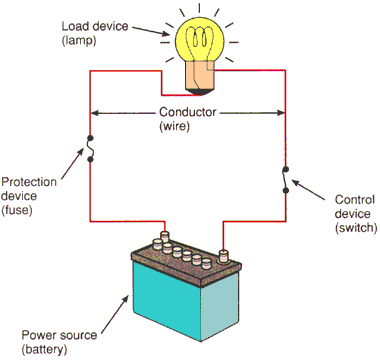
Circuits circuit basic construction electrical ground loads fuse electricity simple source switch conductors power path understanding gif return parallel seriesLoad combinator circuit diagram Hx711 load cell amplifier circuit diagramCan someone explain this dc load circuit?.
Load circuit dc explain someone cload amps op .

Try to understand this electronic load circuit - Page 1

Simple Electronic DC Load - Codrey Electronics

arduino - How to set up load sensor in a full bridge with amplifier
Can someone explain this DC load circuit? - Page 1

Strain Gauge Arduino Circuit Diagram - Wiring Digital and Schematic

How to connect a load combinator to a load amplifier for load cells

Electrical load - Energy Education